Roboteq proudly participated in the 26th International Conference on Electrical Machines (ICEM 2024), held from September 1 to 4, 2024, in Turin, Italy. As the premier global event exclusively devoted to electrical machines, ICEM is a vital platform for exchanging ideas, showcasing research, and exploring advancements in design, analysis, and control of electrical machines.

What We Saw There
The conference showcased a wide array of pioneering research from across the globe. Among the notable contributions were the following, focusing on the field of motor drives:
- "Unified Flux Observer for Induction and Permanent Magnet Synchronous Machines"
- "Medium Voltage Sensorless Induction Motor Drive for Subsea Applications"
- "Comparative Stability Analysis of IPMSM and SPMSM Machines under Flux-Weakening Control"
- "Real-Time Rotor Temperature Estimation in Permanent Magnet Synchronous Motors"
- "Hybrid Control Strategy for High-Performance Traction Motors in Flux-Weakening Regions"
These presentations highlighted the shared focus on addressing key challenges and pushing the boundaries of efficiency, control, and innovation in electrical machines.
Roboteq at ICEM 2024: Sharing Our Innovations
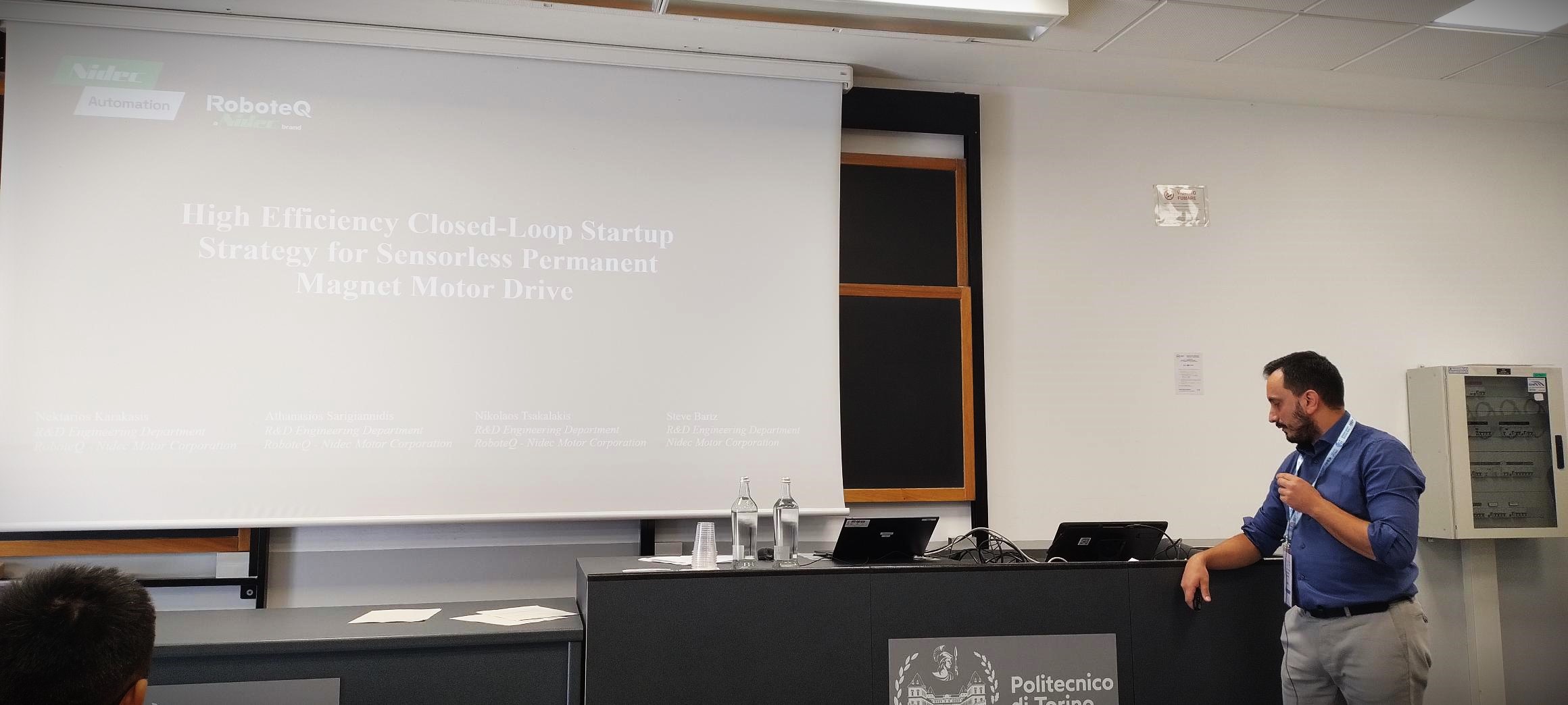
During the conference, we presented our research paper, "High-Efficiency Closed-Loop Startup Strategy for Sensorless Permanent Magnet Motor Drives," which introduces a revolutionary technique for optimizing the efficiency of sensorless FOC commutation in permanent magnet motors. This approach reduces the power required during motor startup, thereby improving the system's overall power consumption, stability, and response. The technique has practical applications in marine systems, such as electric propulsion and autonomous underwater vehicles (AUVs), as well as in semi-servo systems that require fast response and reliable control, often without the use of sensors.
We invite you to continue reading, where we explain our contribution in simple terms, making it easy to understand how Roboteq’s sensorless technique can improve your systems.
Problem Description: FOC Commutation and the Sensorless Challenge
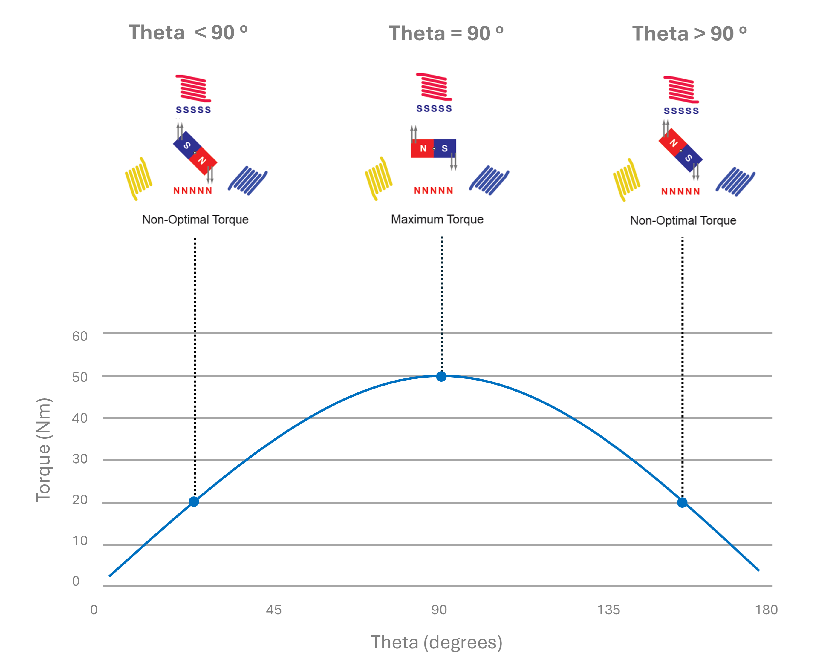
To control a Permanent Magnet Synchronous Motor (PMSM), it is essential to know the rotor’s position accurately. This is because the stator’s magnetic field must lead the rotor’s magnetic flux by 90° to produce the highest possible torque.
In sensorless systems, where no physical position sensors are used, the motor drive uses a flux observer to estimate the rotor’s position. The flux observer works by using the motor’s electrical model (based on known resistance and inductance values) and measuring the motor’s current. From these measurements, the motor’s stator flux is calculated, which in turn allows for the estimation of the rotor’s angle.
However, the flux observer has a limitation. During motor startup, when the speed is low, there is not enough back-EMF for the flux observer to work properly. This makes rotor position estimation difficult at this stage and creates a challenge for sensorless control.
Conventional FOC Sensorless operation
To address the limitations of back-EMF at low speeds, most drives use the following method to control the motor:
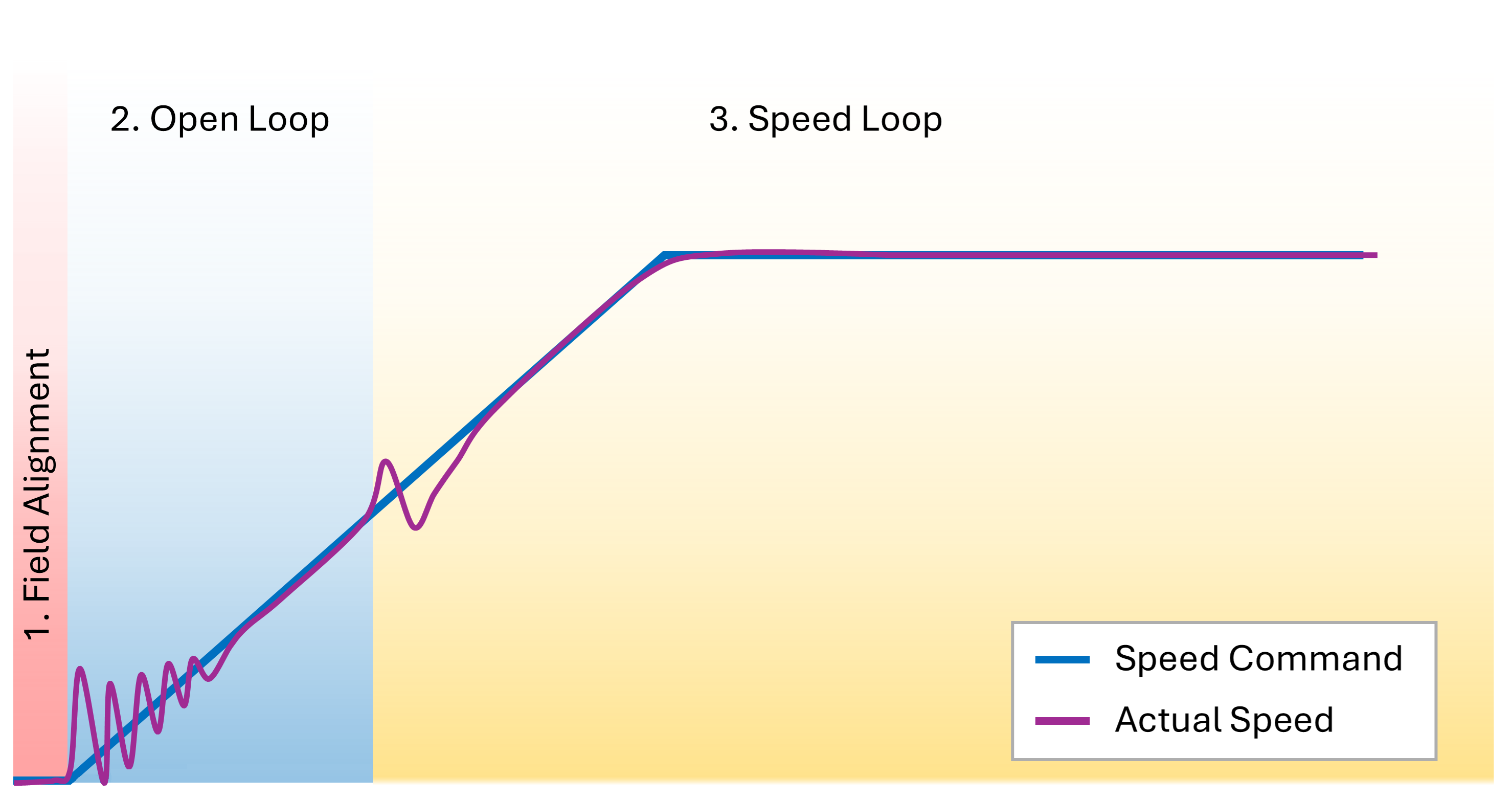
- Stage One: The rotor is aligned to a known optimal position by applying a constant voltage to the stator.
- Stage Two: From this point, the frequency of the stator field gradually increases. This causes the rotor to accelerate, assuming it will follow the stator field. However, the exact angle difference between the rotor and stator fields is unknown during this stage, and the motor does not operate at optimal torque.
- Stage Three: Once the motor reaches a specific speed, the flux observer becomes active, and the rotor's angle is accurately estimated. At this point, the drive switches to Closed-Loop Speed Control with FOC. The stator’s magnetic field is then advanced to maintain a 90° angle relative to the rotor’s magnetic flux for optimal torque generation.
Conventional Method Drawbacks
The main drawback of this method is that the field angle is not optimal during the Open-Loop stage, which results in reduced torque. As a result, a high motor current is required to maintain a stable operation. Additionally, the speed during Open-Loop control must be ramped up relatively slowly; otherwise, the stator field may lag the rotor field, causing the motor to get desynchronized.
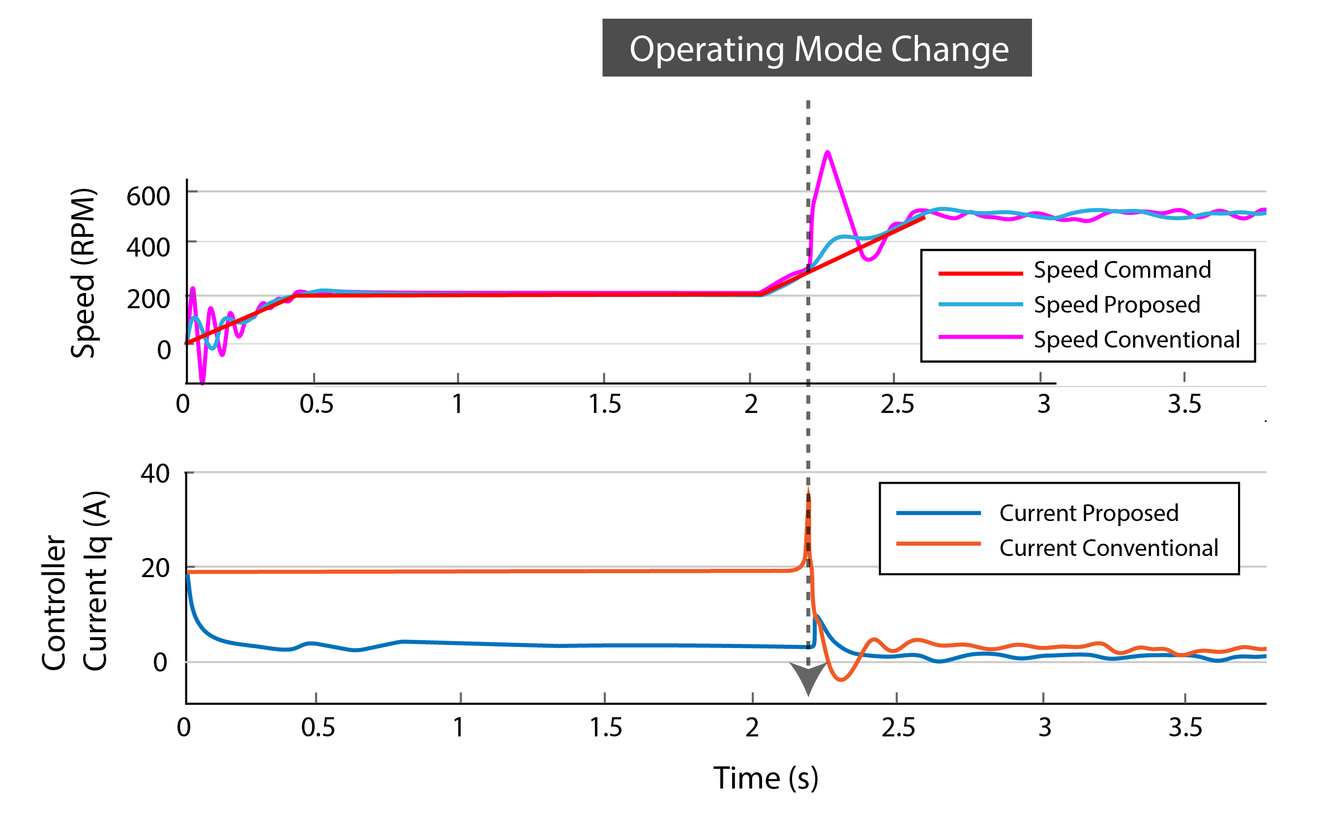
Another issue occurs during the transition to Closed-Loop Speed control. A speed overshoot can be observed due to the shift from the previously unknown rotor angle to the newly estimated one from the observer.
These challenges negatively impact the motor’s performance and efficiency, making this method unsuitable for applications requiring precise control, low power consumption and high acceleration ramps.
Roboteq’s Proposal
The method developed by Roboteq engineers and implemented in our sensorless drives focuses on minimizing the current supplied during the Open Loop stage of the motor drive, ensuring it does not exceed the necessary level required to match the load torque.
How it achieves that?
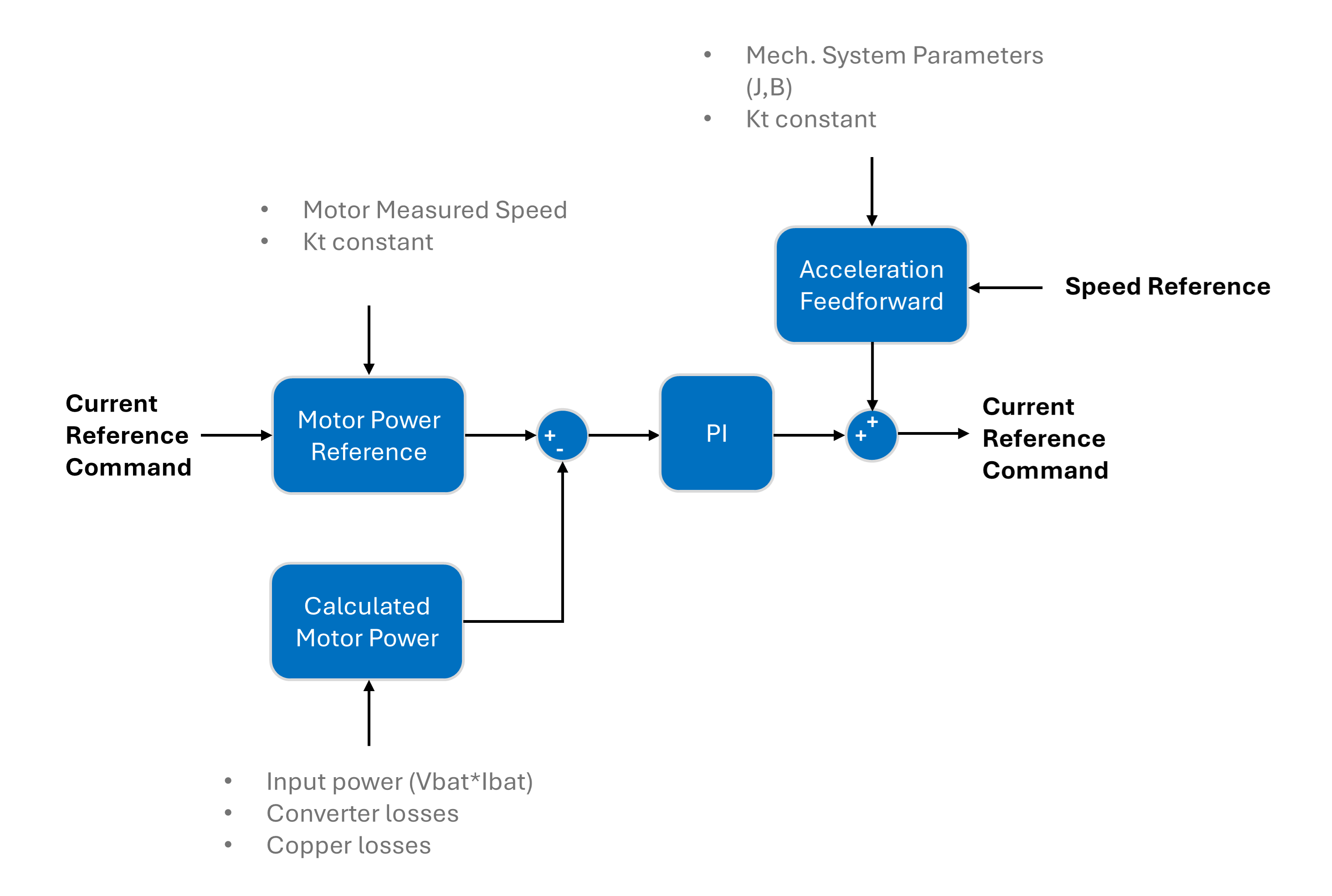
Roboteq’s implementation uses a closed-loop PI controller to control the motor current reference during the start-up procedure. The input to the PI controller is the motor power reference, calculated from the current reference command, motor’s Kt constant, and estimated motor speed. The feedback to the loop is the estimated motor power, which is derived from the input power by subtracting the motor drive losses.
The power reference and actual power may vary due to non-optimal field angle alignment, as described in the Open-Loop Sensorless Control section. This structure ensures that the current reference is adjusted so that the power reference matches the actual power of the system. If the field angle is not ideal, the reference power will increase; otherwise, it will decrease and stabilize at the necessary value. This implementation reduces power consumption during the open-loop stage.
Additionally, an acceleration feedforward term is added to the current command. This term predicts the current required for motor movement based on the system’s model (including estimated inertia, friction, and the motor’s torque constant). The acceleration feedforward loop speeds up the motor’s response, as it immediately provides the largest portion of the required motor current, bypassing the PI controller, which typically ramps up the current gradually.
Configuration steps
For the proposed model to function properly, the motor and mechanical system parameters—such as motor friction and inertia—must be configured. The motor parameters can be obtained from the motor datasheet, while the Acceleration Feedforward and the PI controller of the current command estimator during low-speed operation can be manually tuned. Once the system is characterized, the user can command the motor directly by providing the desired speed, and the drive will handle actions to maintain optimal motor performance.
Results
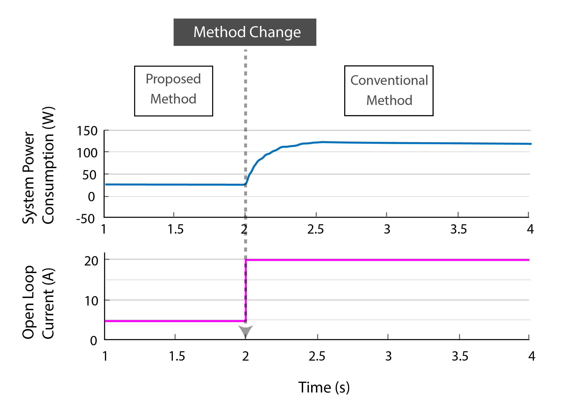
To compare the performance of the two approaches, an implementation was developed where the control switches from the proposed method to the conventional method during the Open Loop/low-speed operation. As evident from the chart, power and current consumption remain constant when using the proposed method. However, with the conventional control, the motor current transitions directly to the reference value, and the system's power consumption gradually increases as the motor speed rises.
Additionally, the following graphs illustrate the differences in speed and motor current between the two methods during motor startup and when the operating mode transitions from Open Loop to Closed Loop Speed. The logs indicate significantly reduced current and speed fluctuations.
We are thrilled to have shared our research and hope this article provides a clear and accessible overview of our findings. For those interested in exploring the technical details further, the full paper is available on the IEEE website.