This article presents and explains the key contributions of Roboteq’s recent paper, Electromechanical Oscillations Angle Compensation (EOAC) Technique for Sensorless Permanent Magnet Motor Drive, which was presented at the 2025 IEEE Workshop on Electrical Machines Design, Control and Diagnosis (WEMDCD), held on April 9–10 in Valletta, Malta.
The paper introduces EOAC, a novel method designed to mitigate electromechanical angle oscillations that commonly occur during the startup phase of sensorless permanent magnet motor (PMM) drives. By applying real-time angle compensation based on power analysis, the technique significantly improves startup reliability and reduces speed ripple—addressing a persistent challenge in sensorless motor control. This article aims to make the core concepts and results of the paper accessible to a broader technical audience, highlighting both the theoretical approach and the practical outcomes demonstrated through simulation and experimental validation.
How Sensorless Commutation Works in PMSMs
To eliminate the need for physical sensors, sensorless control algorithms in permanent magnet synchronous motors (PMSMs) rely on flux estimation. This estimation uses the motor’s mathematical model, along with measured currents and speed, to determine the rotor’s electrical angle—an essential parameter for applying the correct voltage and ensuring proper commutation.
When starting from standstill, the motor drive typically operates in three stages. The first is field alignment, where the rotor is magnetized and aligned to a known starting position. At this point, the initial rotor angle is known. Next comes the open-loop commutation, speed mode stage. Since the back electromotive force (EMF) is still too weak for accurate flux estimation, the motor is driven with a predefined frequency profile, assuming the rotor will follow. However, torque production is suboptimal in this phase. Once the motor reaches a certain speed threshold, it transitions to the third stage: closed-loop speed control, where the flux estimator becomes reliable and sensorless estimated angle and feedback take over.
The Challenge
During the open-loop stage, the rotor position is not directly measurable, leading to uncertainty in the alignment between the stator and rotor magnetic fields. Since optimal torque is produced when the fields are perpendicular, any deviation results in fluctuating torque. These torque fluctuations, influenced by the load, reinforce mechanical vibrations and lead to speed ripple. While some level of speed fluctuation is expected, more severe consequences—such as failed startups, overcurrent, or stalling—can occur. Additional disturbances may also arise during the transition from open-loop to closed-loop control, further affecting system stability.
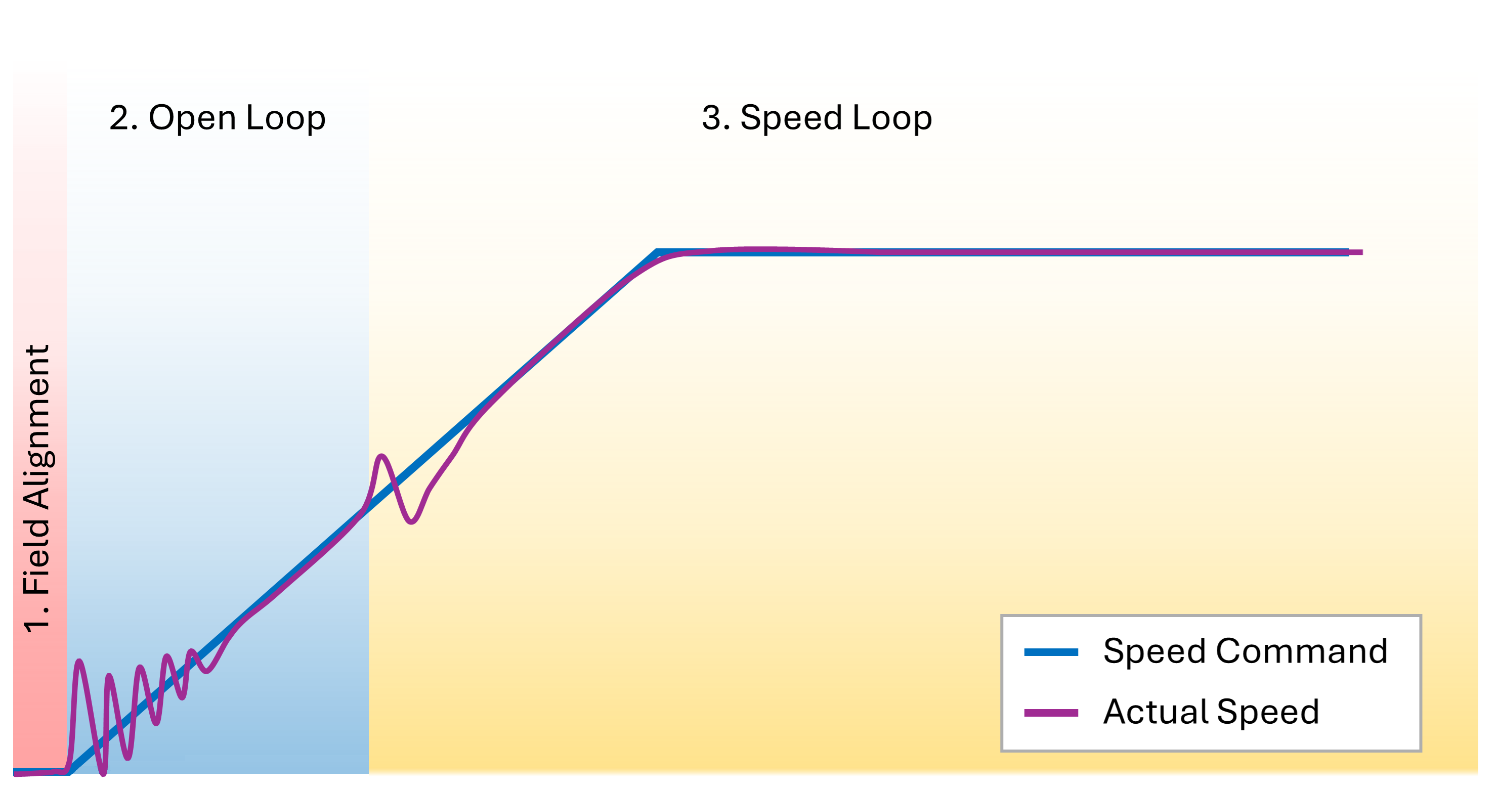
Figure 1. Sensorless motor control stages
Detecting fluctuations and applying correction
As mentioned, during the Open Loop stage, speed measurement and angle estimation are unreliable, making it difficult to directly detect speed fluctuations. At this stage, the only variables that can be accurately measured are the input current and voltage, from which the input power is calculated. The motor drive then estimates the actual output power by subtracting the expected losses in the converter and motor windings.
A mismatch between the reference power and the estimated output power indicates variations between the stator and rotor magnetic fields, which, as previously discussed, affect the output torque. The angle deviation can be determined by comparing the two power values. This deviation is then added to the angle reference to apply a correction and improve control accuracy.
EOAC Block Diagram explanation
The following block diagram illustrates the correction algorithm:
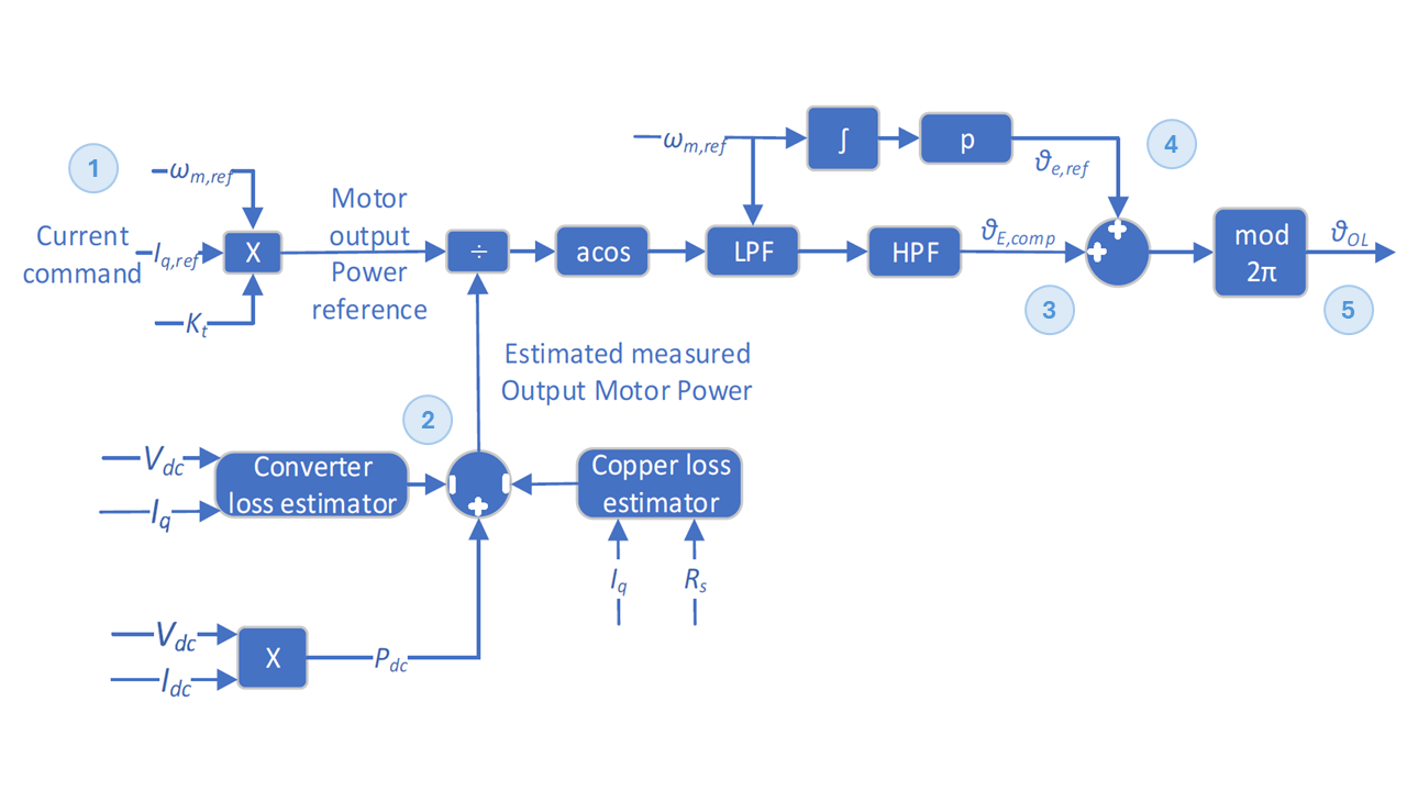
Figure 2. Block diagram of the EOAC technique
Explanation of the Main Components:
- Reference Power Calculation: The reference power is calculated using the reference speed, reference current, and the motor’s torque constant (Kt).
- Actual Power Estimation: The actual power is estimated by subtracting copper and converter losses from the calculated input DC power. This calculation requires the motor resistance to be set by the user. Other parameters are either measurable by the drive or known from the motor drive manufacturer.
- Angle Difference Calculation: The angle difference is obtained using the expression ACos(Reference Power / Actual Power). This signal is then filtered: a low-pass filter removes high-frequency noise, and a high-pass filter removes the constant component—since we are only interested in oscillations, not steady-state angle offsets.
- Reference Angle Generation: The reference angle is generated by integrating the reference speed over time.
- Angle Normalization: The calculated angle is wrapped using modulo 2π to ensure it remains within valid bounds.
The following table details the relevant parameters:
| Parameter | Description | Source |
| ωₘ, ref | The mechanical angular speed reference (rad/s) | Motor drive control |
| Iₘ, ref | The motor current reference (A) | Motor drive control |
| Kₜ | The motor’s torque constant (Nm/A) | Motor Datasheet |
| V_DC | The input voltage, measured (V) | Motor Drive measurement |
| I_q | The motor quadrature current (A) | Motor Drive calculation |
| I_DC | The input current (A) | Motor Drive measurement |
| R_s | The motor’s phase resistance (Ohm) | Motor Datasheet |
| P_DC | The input DC power (W) | Motor Drive calculation |
| Θₑ, ref | The rotor angle reference (degrees) | Motor Drive calculation |
| Θₑ, comp | The rotor compensation angle (degrees) | Motor Drive calculation |
| Θ_οι | The desired field angle (degrees) | Motor Drive calculation |
Results
Simulation Results
A discrete transient simulation model was developed to analyze and evaluate both the proposed and conventional methods. Two test scenarios were considered: In the first, the motor operates under a light load of 0.1 Nm with a speed command of 200 RPM. In the second, the motor is subjected to a 2 Nm load with an initial speed command of 50 RPM—where the motor still operates within the open-loop control stage—which is later increased to 200 RPM.
The simulation results confirm the improved performance of the proposed method. In the first scenario, oscillations were significantly reduced. In the second, while the conventional method led to motor desynchronization, the proposed approach enabled the motor to stabilize successfully. Additionally, in the first scenario, the comparison between the calculated and reference motor power waveforms illustrates how the proposed method effectively reduces power fluctuations.
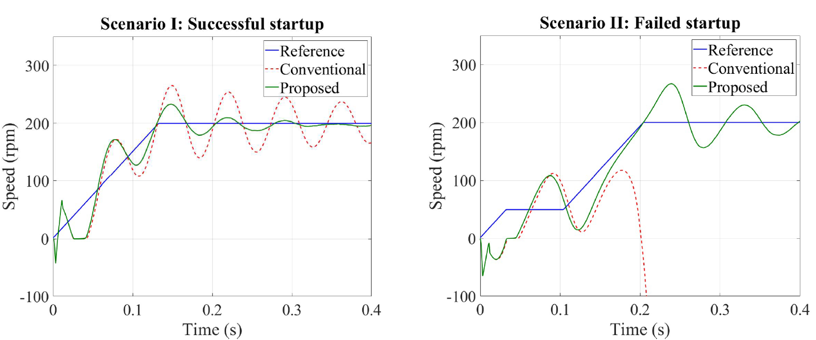
Figure 3. Conventional versus proposed method speed response for test scenario I and test scenario II
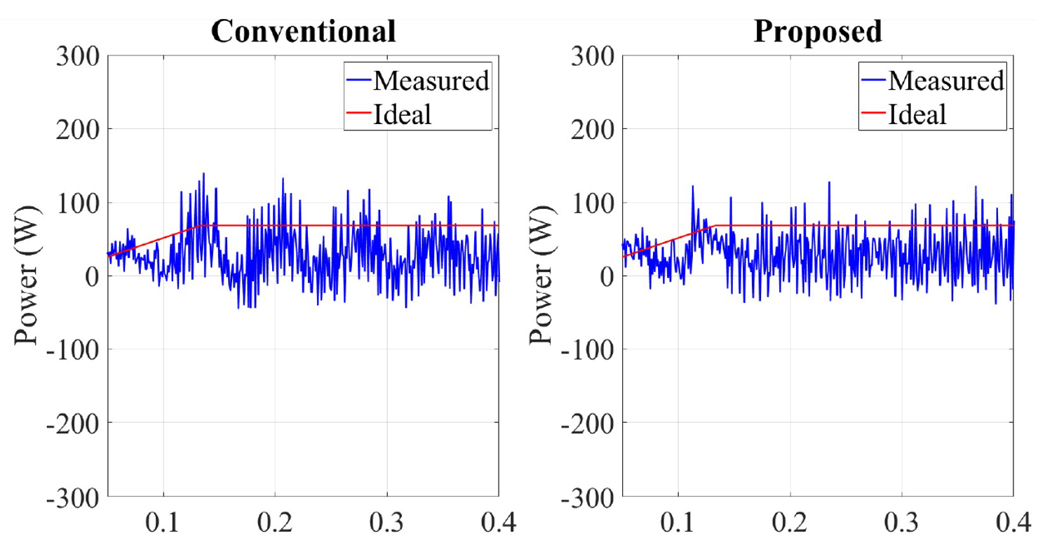
Figure 4. Conventional versus proposed method three phase active power for test scenario I.
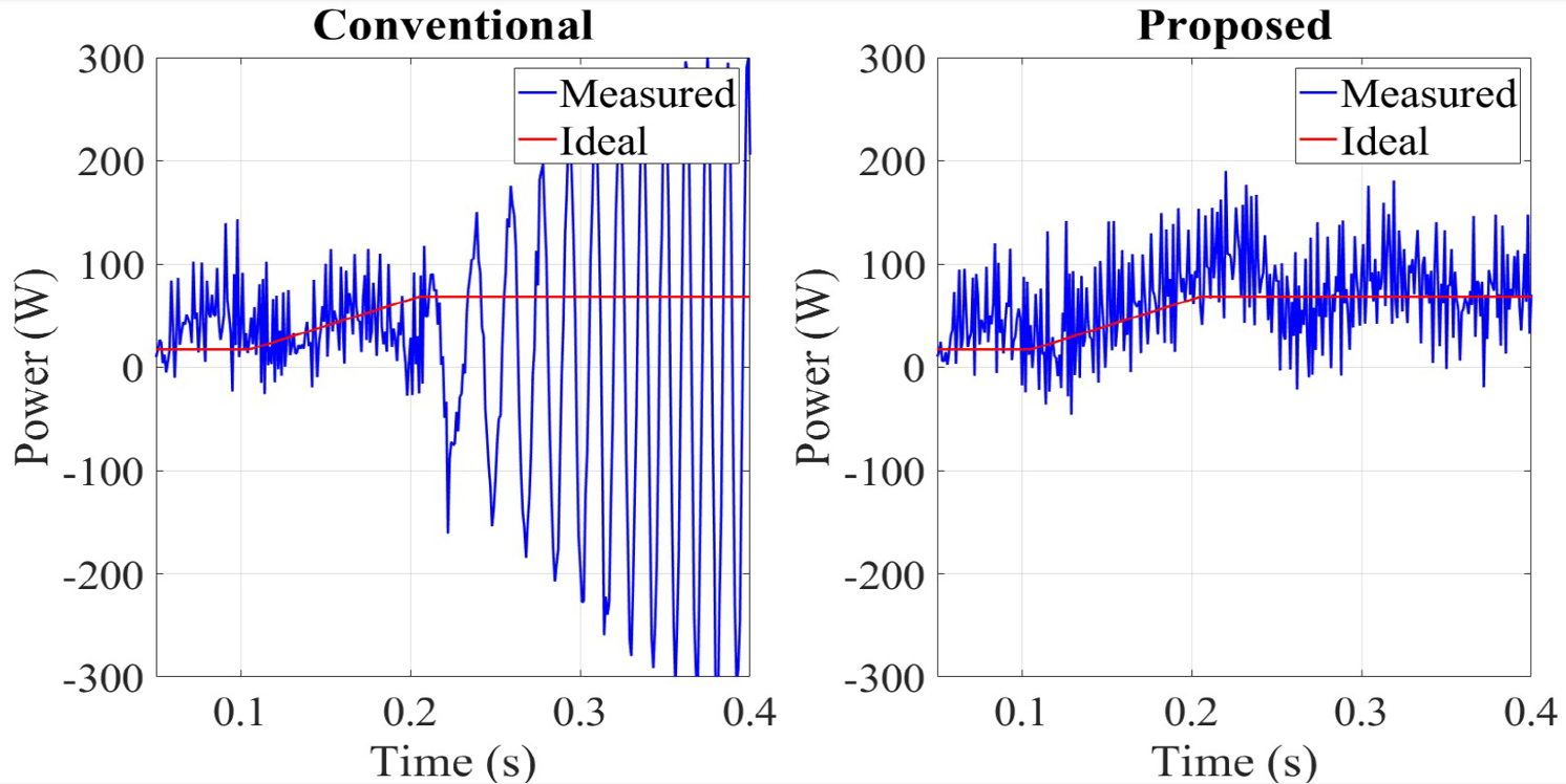
Figure 5. Conventional versus proposed method three phase active power for test scenario II.
Experimental Results
The experimental setup consists of two identical, coupled Nidec permanent magnet motors. One operates in sensorless speed control mode using an SBLG2360T drive, while the other functions in torque mode using an FBLG2360T drive, serving as the load. In addition to acting as a load, the second motor is used to accurately measure the speed of the coupled system, as it is equipped with Hall sensors.
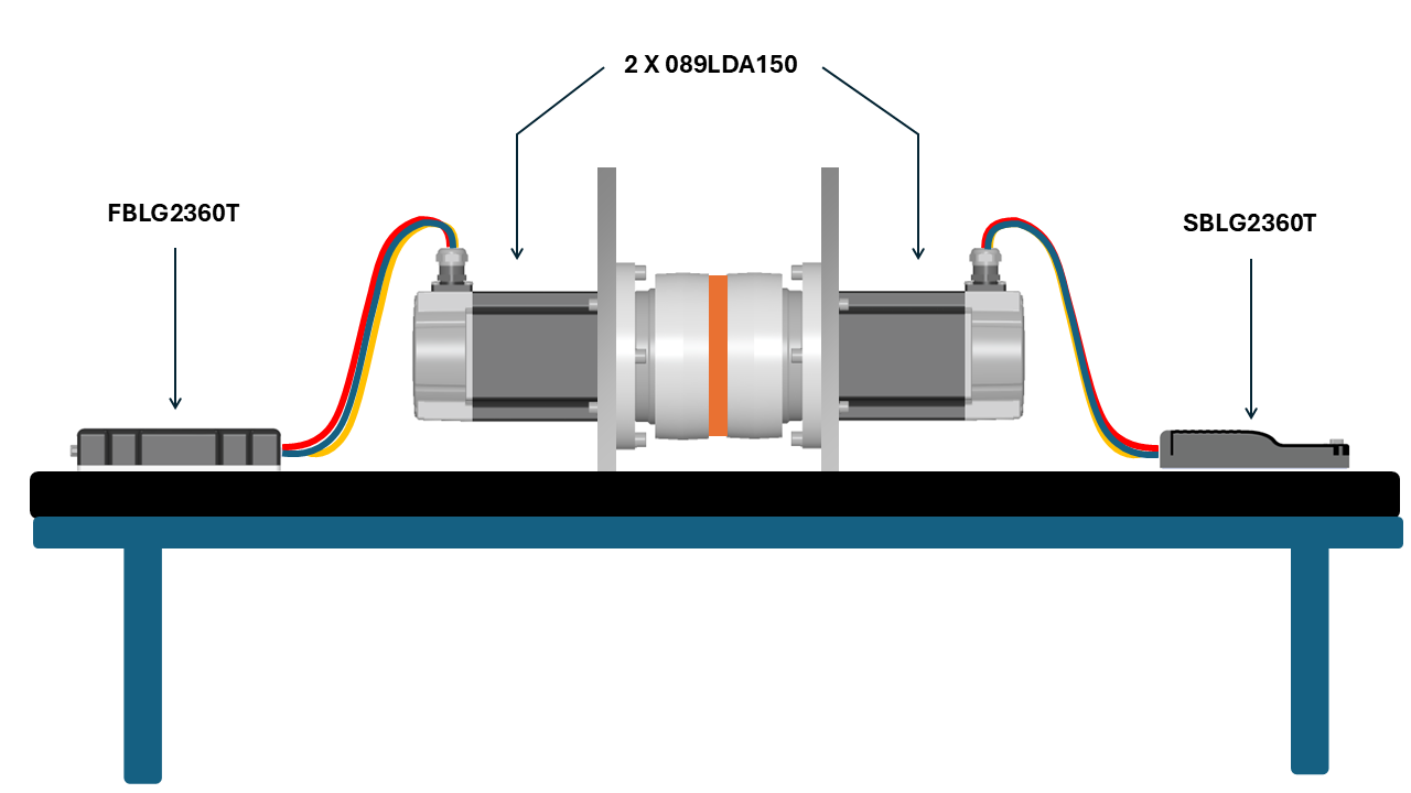
Figure 6. Illustration of the test setup
Similar to the simulation, two different scenarios were tested: the first involved a speed command of 200 RPM, and the second was a case where the motor failed to start. The experimental results closely matched the simulation, showing a significant reduction in oscillations—from 35 RPM to 5 RPM—in the first scenario, and successful motor commutation in the second scenario, where the traditional method failed and the motor became desynchronized.
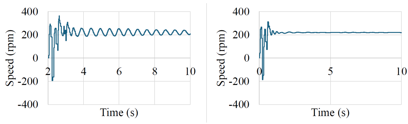
Figure 7. Comparison of conventional (left) versus proposed method (right) actual motor speed for scenario I.
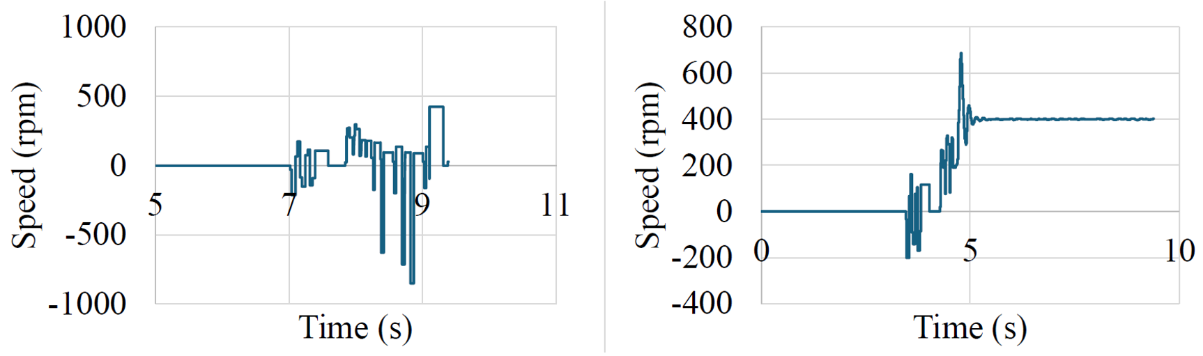
Figure 8. Comparison of conventional (left) versus proposed method (right) actual motor speed for scenario II.
Conclusion
In this research, a new method for efficiently compensating electromechanical angle oscillations during the startup of sensorless permanent magnet motor (PMM) drives has been successfully introduced. The proposed approach uses a real-time angle compensation strategy based on the measured and ideal motor output power, developed through a systematic analysis of the root causes of electromechanical vibrations during open-loop sensorless startup. The calculated oscillation angle is then effectively added to the reference electric angle. The controller design, along with both simulation and experimental results, demonstrated the effectiveness of the proposed EOAC method. Specifically, it achieved an 80% reduction in speed ripple during steady-state operation and a higher rate of successful startups under more demanding conditions—marking a significant advancement in motor drive technology.
The paper can be downloaded from the IEEE digital library