Electromagnetic interference (EMI) is any unwanted electromagnetic disturbance that interrupts, obstructs, or degrades the performance of electronic devices. In automated systems such as robotics and AGVs, EMI can affect communication, sensors, and control electronics.
The main ways that a disturbance is transmitted from its source to an affected circuit are:
|
|
Conductive Coupling: EMI travels through direct electrical contact between circuits or components, such as shared conductors or ground paths. Proper grounding and isolation techniques are essential to minimize this form of interference. |
|
|
Inductive Coupling: A changing current in a conductor creates a magnetic field around it. If another conductor is nearby, this changing magnetic field induces a voltage in it according to Faraday’s law of electromagnetic induction. |
|
|
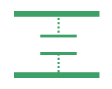
Capacitive Coupling: Any two conductors placed close to each other inherently create a parasitic capacitance. When the voltage on one conductor changes, this capacitance allows a displacement current to flow, coupling the signal to the other conductor. |
|
|
Radiated Coupling: When currents and voltages change rapidly, they generate electromagnetic fields that can propagate through space as radio waves. These fields can induce voltages in nearby circuits without any direct physical connection. |



Sources of EMI in Mobile Robots
The following table summarizes the main sources of electromagnetic interference in any mobile robot, along with a short description and the primary coupling mechanism through which the disturbance propagates.
Table 1. Types of EMI
|
Source |
Description |
Type |
|
Power Stage |
High-frequency switching events generate common-mode currents that couple to the heatsink via parasitic capacitance between MOSFET drains and the heatsink surface. |
Capacitive Coupling |
|
Motor |
Parasitic capacitance between motor windings and the motor housing transfers switching noise to the chassis. |
Capacitive Coupling |
|
Microcontroller & Clock Circuits |
High-frequency clock signals from the MCU can emit EMI if not properly decoupled or shielded. |
Radiation |
|
Communication & Position Sensor Signals |
Low-voltage, high-frequency signals used for communication and feedback can emit and receive EMI. |
Radiation |
|
Motor Cables |
PWM signals on long motor cables act as antennas, radiating high-frequency noise into the environment. |
Radiation |
|
Motor Cables |
High current spikes in motor cables induce voltages in adjacent cables through magnetic fields. |
Inductive Coupling |
|
DC Power Input |
High current transients during load changes create voltage ripple on the DC bus which can inject noise into other circuits via inductive and capacitive paths. |
Conductive Coupling |
|
Other Equipment |
Switching transients from circuits like relays induce EMI if not suppressed with snubbers or flyback diodes. |
Inductive Coupling |
EMI Mitigation Techniques
To mitigate EMI, the following techniques should be applied, focusing on equipotential bonding, proper cable routing, effective cable shielding, and shielding of power inputs and motor phases.
1. Equipotential Bonding for EMC
Equipotential bonding connects conductive parts of equipment to the same potential, reducing voltage differences that cause EMI and improving safety. It includes main bonding and local bonding, both important for EMC and electric shock protection.
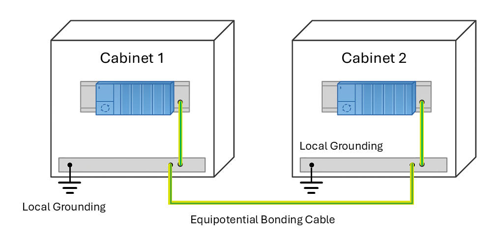
Figure 1. Equipotential Bonding
Key Principles:
- Low Impedance: Use short, low-impedance connections (braids, bolts) for EMC. FE (Functional Earth) wires should match power cable size and be as short as possible.
- Large Contact Area: Ensure wide, secure connections to minimize resistance.
- Corrosion Protection: Prevent corrosion at bonding points to maintain low resistance.
- Minimize Loop Area: Route cables and bonding conductors to avoid large loops that act as antennas.
- Avoid Ground Loops: Use a central bonding point to prevent unwanted current paths.
Motor Drive Recommendations:
- Mount battery housing, power supply frame, motor drive plate, and motor housing on one metal surface or interconnect them with FE and low-impedance braids.
- Place the motor drive close to the motor to reduce cable length and loop area.
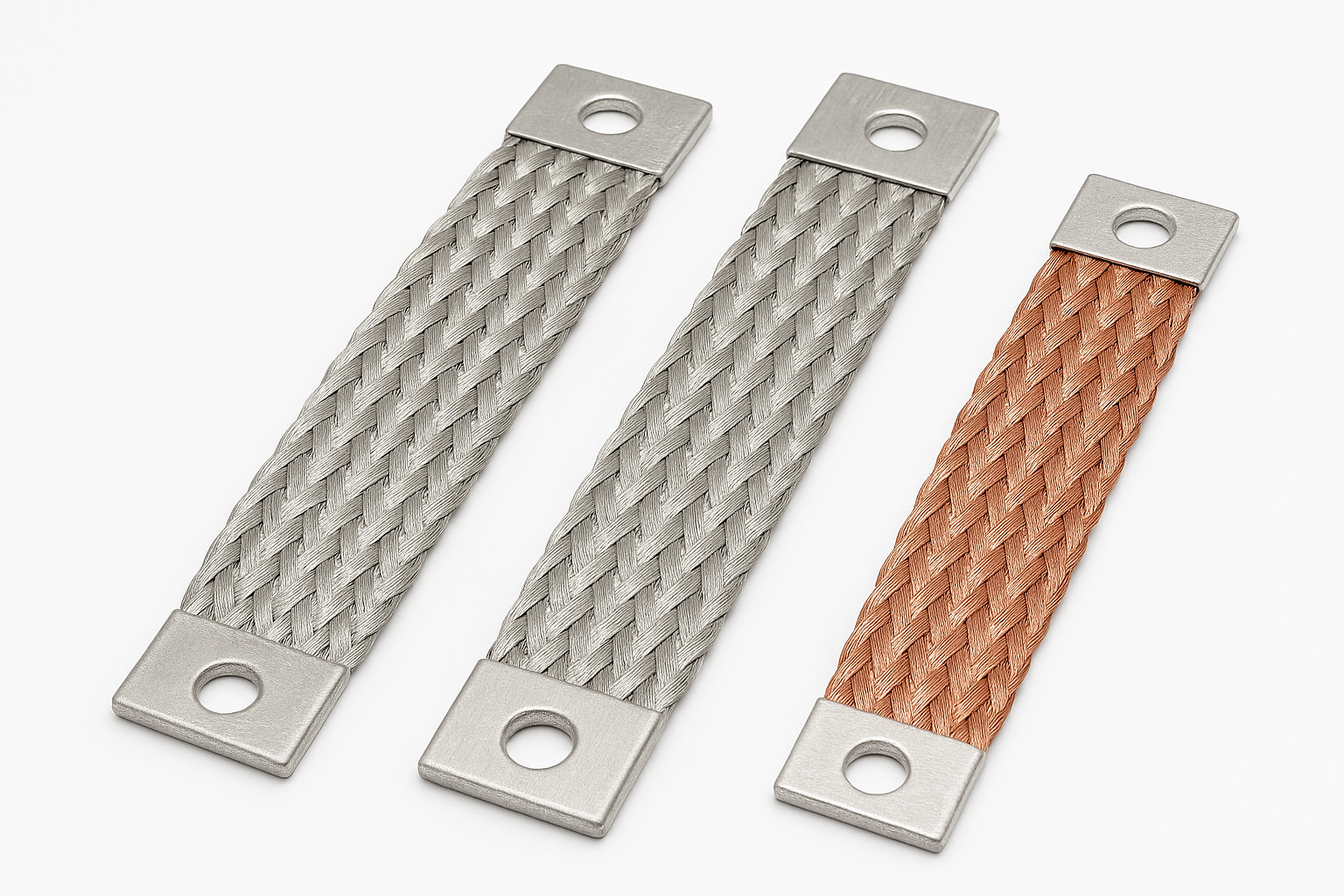
Figure 2. Braided Grounding Straps
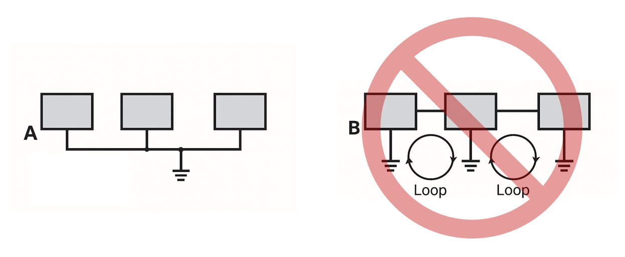
Figure 3. Avoid Ground Loops
2. Cable Routing and Placement for EMC
Cable routing is important in minimizing the electromagnetic interference. For optimal results follow the next guidelines for the motor, DC input and control signals:
Motor Cables:
- Twist the three motor phase conductors together to minimize differential-mode loop inductance.
- If twisting is not possible, route the cores in parallel and as close as possible to the equipotential bonding conductor.
- Keep motor cables away from DC power input cables, position sensors, and communication lines.
- If proximity is unavoidable, route motor cables orthogonally to other cables, not in parallel.
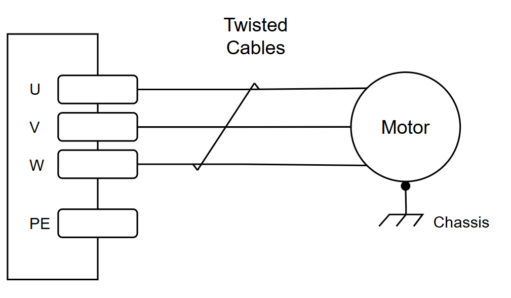 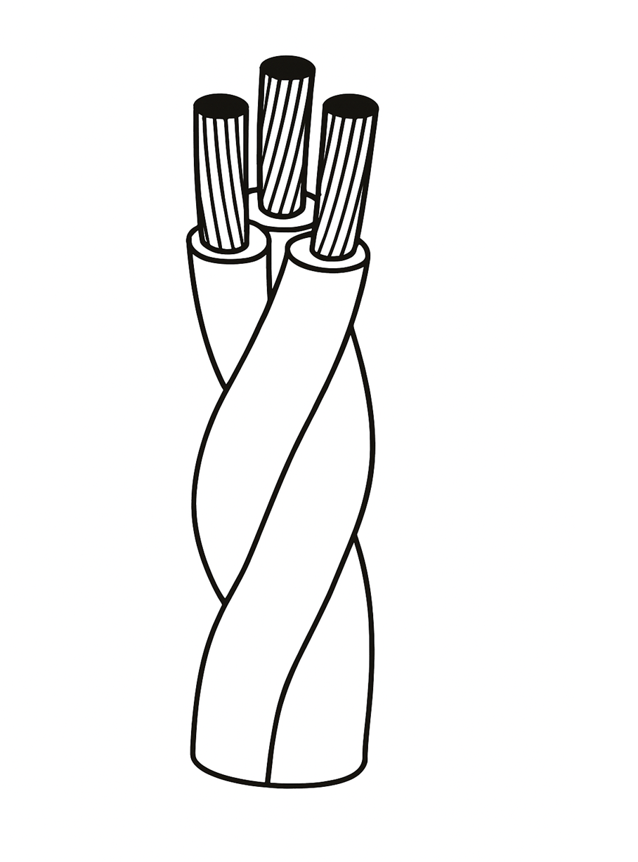 |
Figure 4. Motor Cables Placement
DC Power Input Cable:
- Configure DC power input cables as a twisted pair to reduce loop inductance.
- If twisting is not feasible, route them in parallel, close together, and near the equipotential bonding conductor.
- Never route DC power cables in parallel with motor phase cables to avoid inductive coupling.
|
|
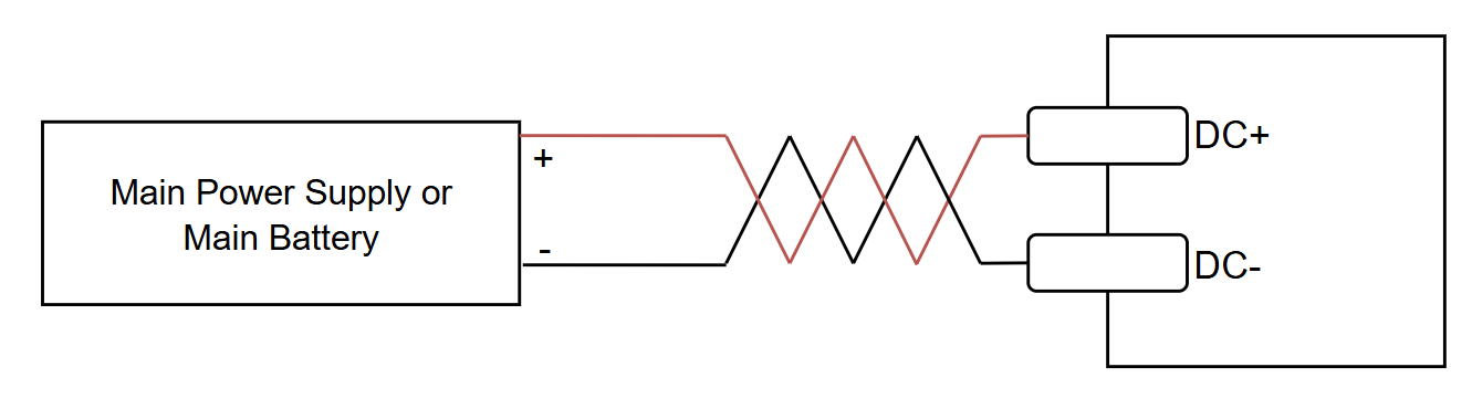
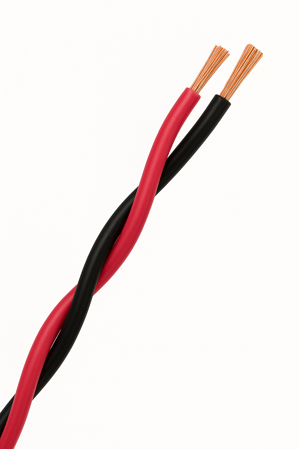
Figure 5. DC Input Cables Placement
Signal and Communication Cables:
- Position sensor lines, motor thermistor cables, and communication signals (CAN, RS485, Ethernet) should be routed far from motor cables which are the primary source of EMI.
- If close proximity cannot be avoided, route them near the equipotential bonding conductor and avoid running them in parallel with motor cables, which can lead to capacitive coupling.
3. Cable Shielding for EMC
Shielding provides a conductive barrier around cables or components that blocks or reduces electromagnetic interference (EMI) by preventing unwanted electric and magnetic fields from coupling into sensitive circuits.
Motor Cables Shielding:
- Apply an electromagnetic shield to motor phase cables to minimize capacitive coupling.
- Bond the shield to system earth via the equipotential bonding network.
- For best performance, terminate the shield at both ends (motor and drive) using 360° metal connectors and metal enclosures. This dual-ended termination enhances immunity against both capacitive and inductive coupling
- Use 360° metal connectors. If 360° termination is not possible, connect the shield directly to the bonding surface using conductive rings, clips, or screws.
- Use Metal enclosers for both motor and drive
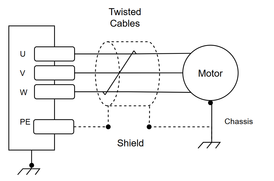
Figure 6. Shielding of Motor Phases
DC Power Input Cable Shielding:
- Shield DC power input cables to reduce capacitive coupling and improve EMC.
- Bond the shield to system earth and terminate at both ends (power source and motor drive).
- Use 360° shielded connectors for low impedance. If 360° shielded connectors are not available use direct bonding to the equipotential surface.
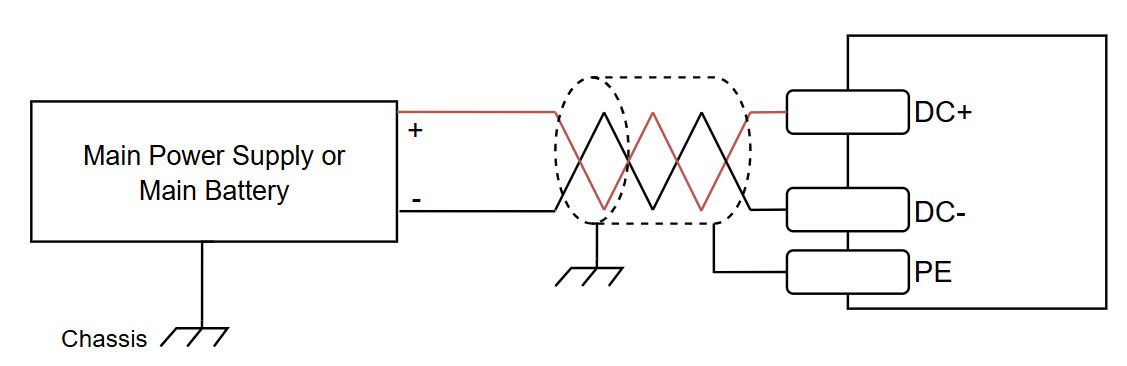
Figure 7. Shielding of DC Supply Cables
Best Practices for DC Power Input and Motor Phase Cable Shielding:
The following image illustrates how cable shielding should be implemented on the chassis, using metal saddle clamps.
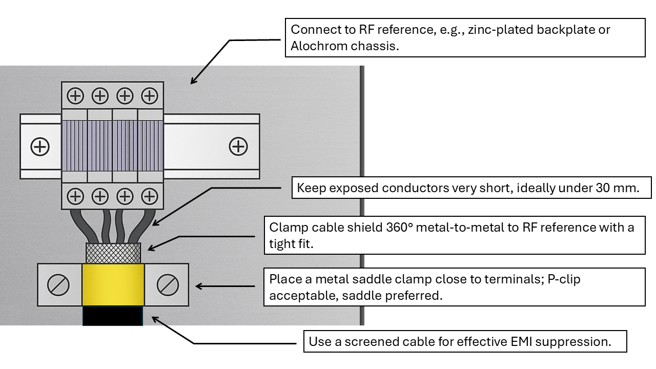
Figure 8. Example of Saddle-Clamp Screen Bonding
Position Sensor & Motor Thermistor Cable Shielding:
- Shield these cables when routed near motor phase or DC power cables.
- Terminate the shield at a single point near the motor drive to prevent ground loops.
- Avoid dual-ended termination for these sensitive signal cables as it may compromise signal integrity due to unintended current flow through the shield.
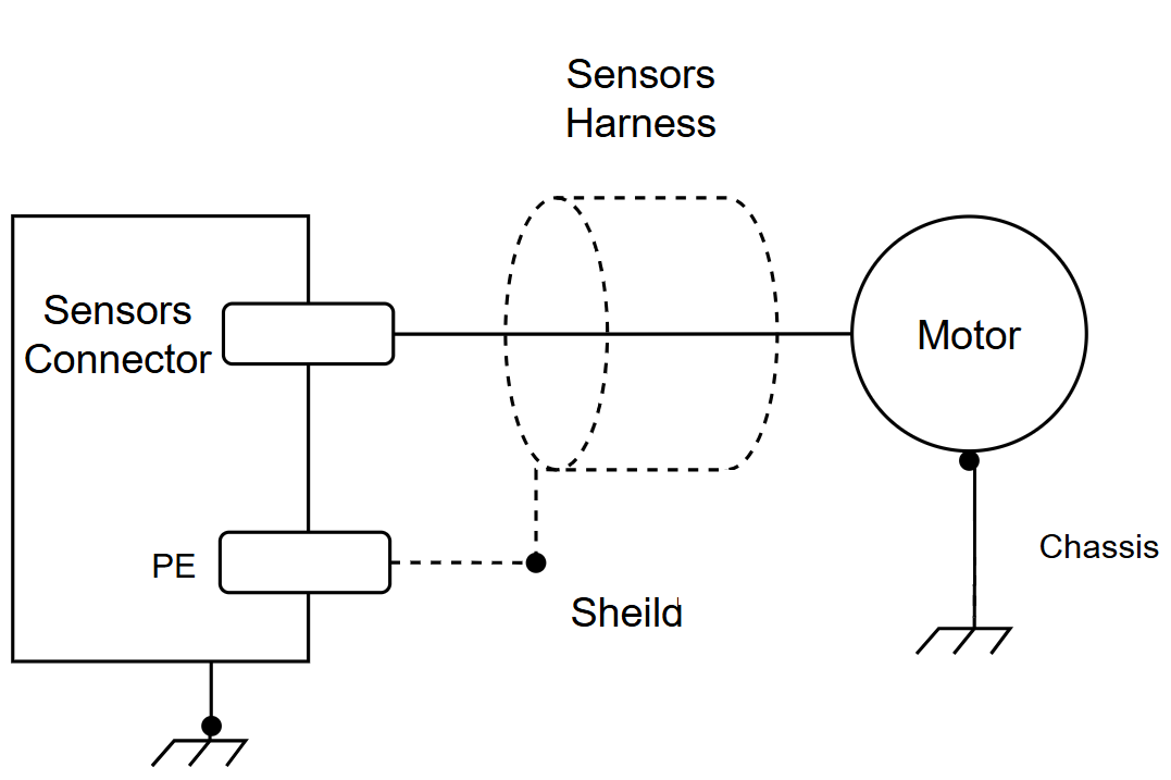
Figure 9. Shielding of Sensors
I/O & Communication Signal Cable Shielding
- Shield communication cables (CAN, RS485, EtherCAT, Ethernet) to prevent data corruption.
- Terminate the shield at both ends (master and slave devices) for continuous low-impedance grounding.
- Dual-ended termination improves immunity against capacitive and inductive coupling.
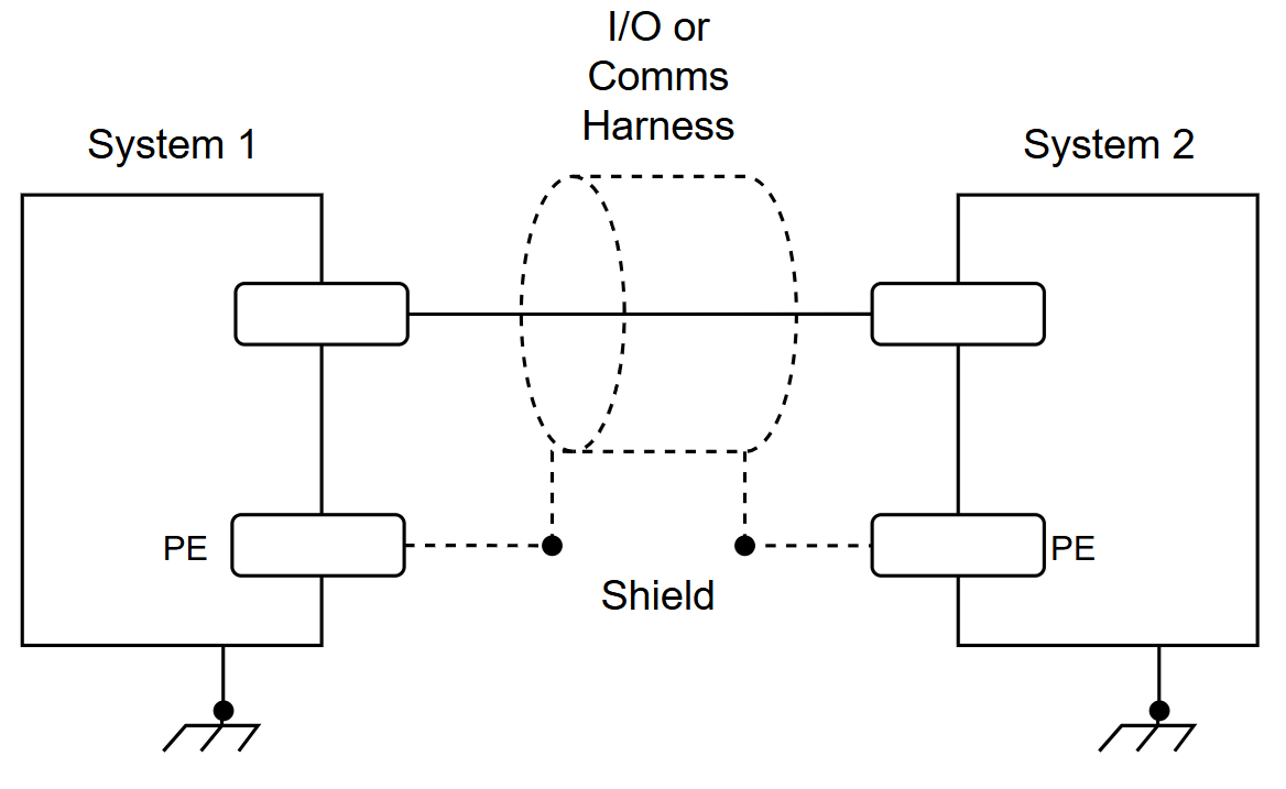
Figure 10. Shielding of Communication Buses and I/Os
4. Motor Phases Filtering
- Use an external common-mode choke when:
- Motor cable length exceeds 2 meters, or
- EMC requirements exceed motor drive certification limits.
- Common-mode chokes attenuate high-frequency noise from the drive’s switching stage.
- In integrated actuators (drive inside motor housing), external chokes may not be needed, but this depends on motor internal design and EMC requirements.
Best Practices:
- Install the choke close to the motor drive.
- Limit cable turns through the choke to one or two (more turns increase capacitive coupling).
- Do not pass the FE conductor through the choke.
- Route cable shields outside the choke.
- Avoid direct contact between the choke core and grounded surfaces.
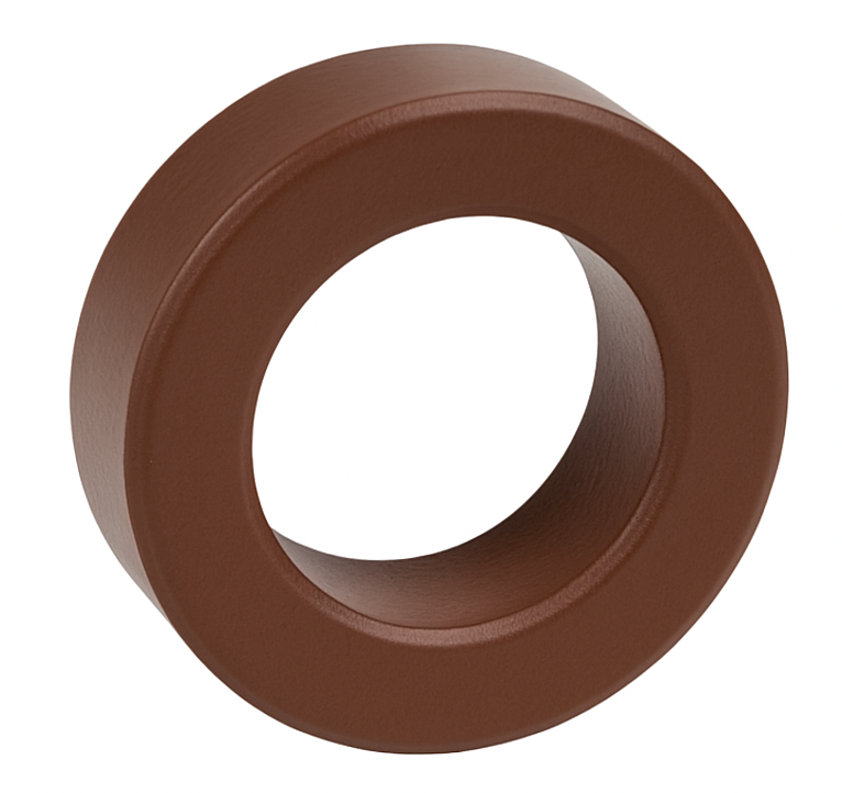 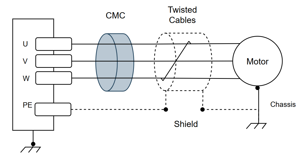 |
Figure 11. CMC Connection on Motor Phases
Suggested Common-Mode Chokes:
|
Manufacturer |
Part Number |
|
Würth Elektronik |
74271151 |
|
Laird Technology |
74271151 28B0773-050 |
|
Laird Technology |
28B0999-000 |
5. DC Power Input Filtering
- Apply a common-mode choke when:
- DC power cable length exceeds 2 meters, or
- EMC requirements exceed motor drive certification limits.
- Chokes suppress high-frequency noise from switching transients, protecting sensitive electronics.
Best Practices:
- Install the choke close to the motor drive.
- Limit cable turns to one or two.
- Do not pass FE conductor through the choke.
- Route cable shields outside the choke.
- Avoid direct contact between the choke core and grounded surfaces.
|
|
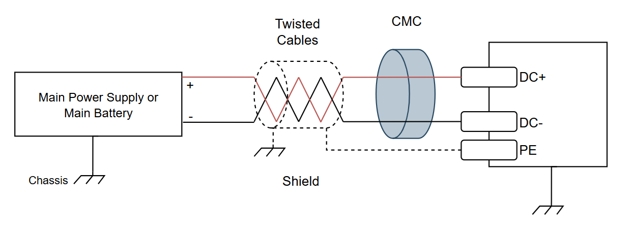 |
Figure 12. CMC Connection on DC Supply
Suggested Common-Mode Chokes:
|
Manufacturer |
Part Number |
|
Würth Elektronik |
74271151 |
|
Laird Technology |
74271151 28B0773-050 |
|
Laird Technology |
28B0999-000 |